W e offer cathodic protection models for all types of structures and pipelines.
Our engineers are specialized in Corrosion and Cathodic Protection and use a wide variety of software for this purpose to simulate a wide range of structures.The main objective of Cathodic Protection modeling is to demonstrate the actual performance of a Cathodic Protection system and adjust its design helping to reduce the final cost of the installation.
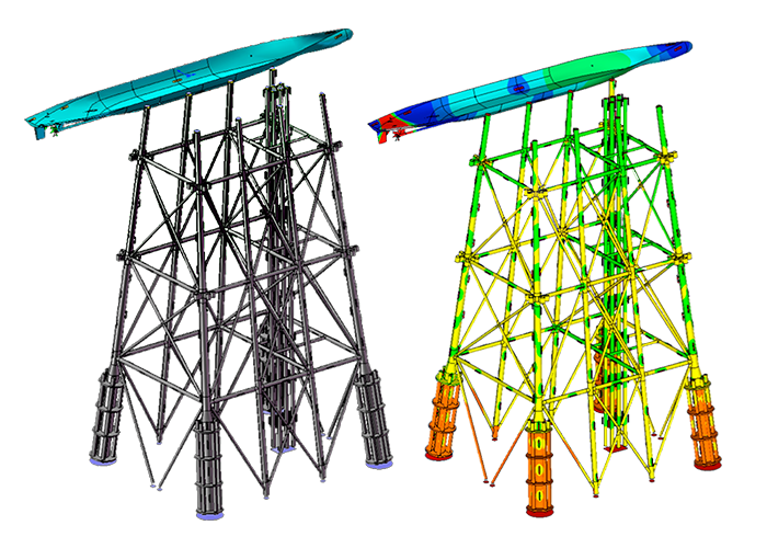
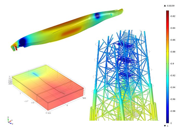
Computer modelling is a mathematical tool in which the chemistry of the environment, the real properties of the materials and the actual electrochemical processes happening in the environment (i.e. soil, seawater) are combined. Consequently, the surfaces of the metal that suffer from corrosion or excessive protection against corrosion are disclosed and can be observed in 2D or 3D dimensions. With this scientific approach, the performance of a cathodic protection design can be tested and tuned to achieve the correct protection against corrosion desired on the structure.
In addition, it is known that RP practices indicate with a certain degree of conservativism the required amount of current and anodic mass to protect some given surfaces from corrosion. However, the distribution of this current and/or the anodes is arguably indicated in such documents. Computer modelling can disclose the potential distribution on the surfaces and therefore allows the correct location and distribution of Sacrificial Anodes or the correct distribution and current output of impressed anodes.
Offshore
Environments
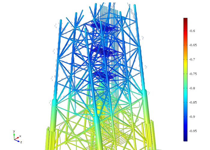
C omputer modelling can help designing not only the cathodic protection systems of subsea structures such oil rigs, wind turbines, pipelines, subsea structures, etc. whether ICCP or SA (Sacrificial Anodes), but also the interaction between different metals without Cathodic Protection. What if situations can be quickly studied and the most suitable design can be determined.
Military and merchant vessels
T
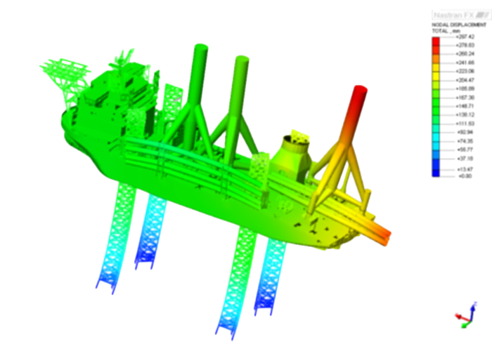
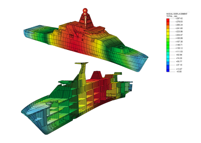
he Cathodic Protection of the vessels provokes Electric and Magnetic Fields around it that are used for signature studies. Computer modelling can determine the magnitude and shape of these signatures, UEP (Under Electric Potential) and CRM (Corrosion Related Magnetics).
Consequently, the Cathodic Protection of the vessel can be adjusted to reduce these signatures and ensure the stealth of the vessel. Cathodic Protection modelling can be used for corrosion control and predict and optimise Corrosion Related Electric and Magnetic signatures for naval vessels. Additionally, computer modelling can be used in the evaluation of Cathodic Protection design options for ballast tanks and other internal structures.
Signature Management
W
WI is widely used by defence organisations worldwide to predict the performance of cathodic protection systems and to minimise the associated electric and magnetic signatures. WWI models the electrochemistry on the metal surfaces of the vessel and the electric fields in the sea water surrounding the vessel using the boundary element method.
The software that WWI uses for Signature Management have been developed to support the needs of its large customer base which consists of most of the world's navies, maritime defence organisations and their supply chain.
- Performance of the CP/ICCP system
- The corrosion related electric signature
- The corrosion related magnetic signature (CRM)
The design of a cathodic protection system is of great interest to defence organisations, not only to ensure the integrity of the vessel, but also because it contributes to the electric and magnetic signature of the vessel.
Electro magnetic signatures are playing an important role in the detection of naval vessels and in the fusing of intelligent mines. The static electric signature is the electric field associated with the DC corrosion or cathodic protection current which flows through the sea water around a vessel.
This is sometimes referred to as the Underwater Electrical Potential (UEP). The corrosion related magnetic (CRM) field is the coupled magnetic field caused by the corrosion related electric currents flowing in the sea water between the SA and the ship hull.
It is important to note that UEP and CRM signatures exist even in the absence of a Cathodic Protection system. They are caused by the galvanic potential differences between the metallic structures in contact with the sea water. For example, the relative position in the electrochemical table of steel and bronze provides a sufficient driving potential to create an electric field.
In order to control the signatures and to preserve the integrity of a vessel, it is essential to be able to predict the impact of the design and operation of the Cathodic Protection system on the electric and magnetic fields.
Onshore Environments
L ikewise, computer modelling can help adjusting ICCP systems in onshore designs or determining the required amount and weight of SA. I.e. onshore pipelines, storage tanks, concrete structures (buildings, bridges) can benefit from the current and potential distributions obtained in the simulations to improve or carry out CP designs.
Interference
C omputer modelling can be used to determine the interference between different structures placed nearby whether these have or not CP based on the metallic properties of each structure. This facilitates the localization of hot spots of corrosion and the trial of mitigation techniques.
Applications
T here are no restrictions on the structure geometry that can be modelled, and these can be offshore, subsea or onshore including shallow coastal waters. Materials include steel - coated or uncoated; other metals; reinforced concrete & hybrid structures. WWI can help determine how the CP system will perform over time so that you can improve the timing and quality of your inspection and maintenance programs. WWI can also be used to predict the service life of Sacrificial Anodes (SA) and the optimum location of ICCP anodes and Reference Electrodes (RE).
OFFSHORE RENEWABLE / OIL & GAS / RETROFIT PROJECT / ONSHORE PIPELINES / TRANSFORMATION PLANTS / MARITIME (Military & Civil vessels) / FPSOs/FSOs, PSOs / OIL&GAS STORAGE FACILITIES / FACILITY PORTS / INDUSTRIAL AND CIVIL STRUCTURES
Typical applications include:
- Validation of CP designs to determine protection potentials provided by the system, anode consumption rates, and service life.
- Optimisation of designs by varying parameters such as anode location, RE location and number of SA, thus reducing cost of design and installation particularly for retrofits and life extensions.
- Investigations of interference effects caused by nearby CP systems, electrical sources, docks, pipelines or other metallic structures.
- Assessment of different operating environments on the effectiveness of the CP system
- Evaluation of the performance of the CP system under various damage scenarios.
- Evaluation of electrical connections/isolations and attenuations on CP system performance.
- Design and optimisation of surveys to improve quality of information and reduce costs.
Benefits:
- Easy visualisation of protection potentials and identification of problem areas
- Clear visualisation of the design and of the protection provided over the life of the structure, thus providing easily understandable verification to clients and design authorities using pictures rather than words and endless tables of results
- Ability to understand and interpret field survey data.
- Models can also be used to simulate and identify the root causes of anomalies in survey data.
- The WWI Wizard enables more effective use of corrosion engineers’ time and expertise by enabling tasks to be performed by the most appropriate staff. CAD engineers can use the tools for model building, while the corrosion expert can take up the model, make changes and assess the results using the Wizard Spread sheet style interface.