Overview
C
orrosion of metals is a naturally occurring electrochemical process that causes the metal to oxidize and deteriorate when exposed to the environment (commonly referred to as rusting.) Cathodic protection (CP) is a means to prevent corrosion by applying a flow of electrical current from an external source (anode) through the environment and on to the metallic structure that is being protected. This protective current changes the environment around the metal thus halting the corrosion reaction. When properly designed and applied, cathodic protection systems stop the corrosion process. Cathodic protection is used to prevent corrosion in a wide range of applications where the structure being protected is surrounded by an environment that allows current flow.
Impressed current cathodic protection systems have the benefit of using an external power supply to drive current. This makes it possible to protect virtually any structure, regardless of size or current requirements using long life anodes and enough appropriately sized power supplies.


Operation
A
lthough modern hull coatings provide some protection against corrosion they do not offer a complete solution.
For this reason, most operators choose to protect their vessels with a purpose designed impressed current cathodic protection system.
Using an arrangement of hull mounted anodes and reference electrodes connected to a CPUs, the system produces a more powerful external current to suppress the natural electro-chemical activity on the wetted surface of the hull.
This eliminates the formation of aggressive corrosion cells on the surface of plates and avoids the problems which can exist where dissimilar metals are introduced through welding or brought into proximity by other components such as propellers and anothers appendix of the hull.
Our Impressed Current system, WWS Aquamatic® v5 Systems works completely autonomously, so it requires practically no maintenance. The system can work in automatic and manual and has an interface for remote communications.
This allows the protection level to be maintained as the seawater resistivity alters. With WWS Aquamatic® v5 Systems protection does not decrease in the range of standard seawater.
An essential feature of WWS Aquamatic® v5 Systems is that they constantly monitor the electrical potential at the seawater/hull interface and carefully adjust the output to the anodes in relation to this.
By installing a WWS Aquamatic® v5 System, operators can make significant savings in hull maintenance costs as well as achieving reductions in fuel costs by having a smooth hull surface. Furthermore, the system will safeguard the owner’s investment and ensure greater safety through stronger hull integrity.
This is achieved through the use of a direct current system generated by one or more automated CPUs, which inject the current produced at impressed current anodes arranged optimally along the hull.
The CPUs receive the readings of the hull potential through reference electrodes that are optimally placed in the hull. These readings are received in the control system which, acting on previously established setpoints, acts on the anodes by injecting current progressively (PID).
In certain areas of the hull, the currents produced by the impressed current anodes are not sufficient to fully protect the entire hull, so it is necessary to place sacrificial anodes that compensate for the lack of current in areas such as sea chest, box cooler, bow thruster, propeller area, etc., is procured.
All the current returns to the hull through the most vulnerable cathodic zones of the same, which are propellers, rudders, fins and appendages.
Therefore, it is very important to have systems that mass these currents with the least possible resistance. For this, grounding systems composed of brushes facilitating the transfer of the current to the hull and cables of appropriate section are used.
Applications
Our systems are designed for sectors such as:
- MARITIME (military & civil vessels)
- OFFSHORE RENEWABLE
- OIL & GAS
- ONSHORE
- REFINERIES
- FACILITY PORTS
- RETROFIT PROJECTS
The power output ranges that we can manufacture range from 50A to 600A, depending on the application required. Other powers and configurations, consult.
The input voltage for our CPUs is 220Vac / 3pH / 50 or 60Hz and we can configure the outputs to 12 or 24Vdc as required and with a ripple content of less than 0.1% in 6 nominal loads OR333.

We use a single control card for two anodes and each card can receive the potential signal of up to two reference electrodes per anode, allowing to obtain a more optimized anode output of each anode. In addition, the cards can receive potential signals from the propeller, rudder, appendices and have an interface for remote communications on board and satellite.
Related products
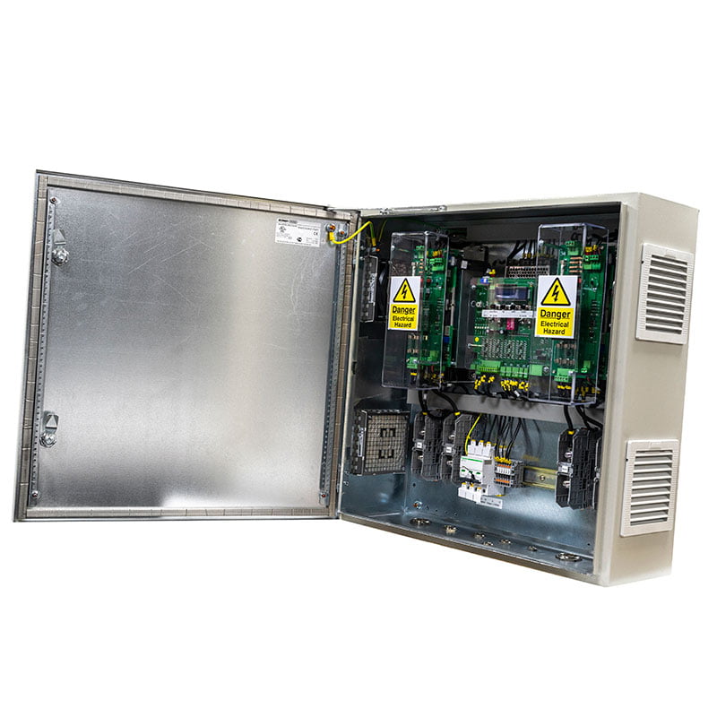
CPU or Control Panel
WWI has made a major advance in ICCP technology with the development of CPU Aquamatic® v5, the intelligent system for naval vessels. Warships require specialised ICCP systems which prevent hull corrosion, but do not interfere with the electrical war-fighting capability of the ship.
With the power modules the network voltage is rectified and a continuous voltage of 300Vdc is obtained at the input of the module. Through an internal high frequency transformer the input voltage of 300Vdc is converted to an output voltage of 12Vdc or 24Vdc as required.
As the size of the transformer is inversely proportional to the working frequency for the same power, the weight and the volume can be reduced considerably while obtaining curling voltages considerably lower than those of a system with thyristors.
The CPU Aquamatic® v5 system is specifically designed to meet the stringent requirements of EMC/EFI, shock, vibration, low maintenance and flexibility of operation in the military environment.
Design Characteristics
- CPUs from 25A to 500A, depending on the application required. Other powers, consult
- Input power 220Vac/50-60Hz & Output 12 or 24Vdc.
- Anodes and Reference Electrodes are easily replaceable during drydocking.
- Ripple Content of less than 0.1%. Measured in the range of 50 – 400Hz to a target accuracy of 0.02%.
- ICCP System can be configured to a two or four zone system.
- Will accept AC Input of +/- 16 to 18% as per Stanag 1008.
- The system is designed for ease of use using a visual command line showing the operational instructions.
- There is a separate visual ‘alarm text line’ which displays any alarm or fault condition in readily understandable text.
- Visual display inside or on door.
- Pin number protected configuration mode prevents unauthorised access to control settings.
- Scrolling display lists all the inputs and outputs of the system together with the operational mode information without the need for any user intervention.
- System can be connected to vessel’s computer network MODBUS RTU or another to allow remote monitoring.
- CPU are mounted in one cabinet. Installation on bulkhead or deck.
- 80% lower weight compared to other TRU.
- 40% lower dimmension compared to other TRU.
- Design in accordance with NES 704 and built to ISO9001 Quality Control.
- Robust design to last the lifetime of the vessel and built to withstand high levels of shock and vibration.
- Minimum maintenance requirements, monthly operational e-reports analysed by WWI engineers.
Alarms Local & Remote
- DC/DC Converter module.
- Corrosion and Overprotection.
- Shaft propeller.
- Rudder, appendix
- Temperature
- Anode
Visual parameters in Local & Remote
- Voltage reference electrodes Pb-St.
- Output voltage anode Pb-St.
- Output current anode Pb-St.
- Control mode (automatic/manual).
- Shaft propeller monitoring.
- Temperature.
- Others (optional).

Cabinet
- IP54 TYPE 12 IK 10, IP66 TYPE 4, 12, 13 IK 10 or TBA.
- Colour RAL 7035 or TBA.
- EMC & Shock and Vibration absorption means silent block, if required.
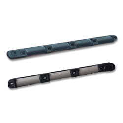
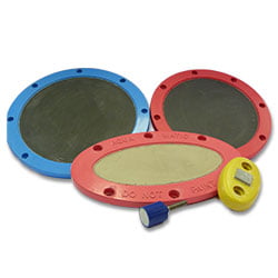
Impressed Current Anodes
WWI has several types and capacities of anodes, depending on the applications required. Circular, elliptical and linear and with capacities ranging from 25A to 300A. Other capacities, consult.
Comprise a Ti-MMO, Pb-Ag, Pt-MMO carrier plate, encapsulated in a glass reinforced resin holder. The anodes are supplied completes with their full cofferdams, cable glands, hull penetration box, metallic plates and dielectric shield material, if required.
The anodes can be changed with the vessel afloat by diver.


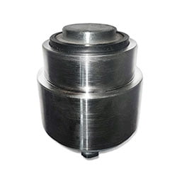
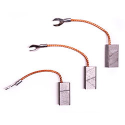
Reference Electrodes
Reference electrodes can be it recessed or surface which comprise a block of high purity zinc (SHG 99.995%) that because of its robust construction and stable electrochemical characteristics is an ideal material for reference purposes.
These are supplied together with their neoprene and teflon sleeves, hull penetration boxes and full cofferdams, if required.
Depending on customer requirements, referenced or surface reference electrodes can be manufactured.

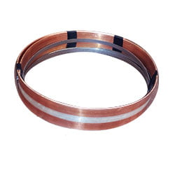
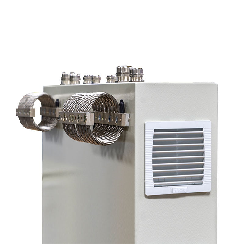
Shaft Earthing System
The propulsion shaft earthing system is carried out by friction brushes of very high conductivity, facilitating the return of the current to the hull by closing the circuit. Our brushes are silver - graphite placed on double brush holders. The contact between the brushes and the shaft is made by means of a slip ring which has a high conductivity copper band inserted.
Also and if the client requires it, a third brush is installed that makes the monitoring function that connects to the CPU.